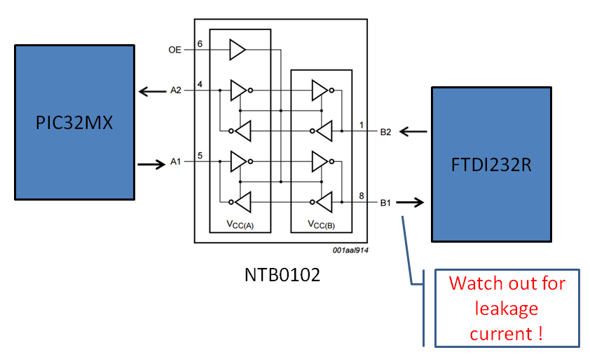
A common design task is to translate between voltage domains or "level shift" for various signaling schemes. In particular connecting UARTs together, for example and FTDI232R is commonly used in USB <--> Serial adapter cables and an NXP NTB0102 dual suppl translating transceiver with auto direction sensing and 3-state output enable.
Generally the TX of the UART pulls high to indicate a stop bit (no transmission) on start-up and the RX pin should be weakly pulled down to prevent spurious bits.
Generally the TX of the UART pulls high to indicate a stop bit (no transmission) on start-up and the RX pin should be weakly pulled down to prevent spurious bits.
However on some devices (in this case the FTDI232R) there is a stray leakage voltage on the RX pin that keeps the pin pulled High on start-up. This is normally not a problem since a strong driver will overcome this weak pullup. With a level shifter generally there are pullup resistors on the inputs and outputs that establish initial voltage levels and will over-ride the weak RX pullup.
With the NTB0102 the auto-directions sensing circuit incorrectly senses this stray voltage on the RX input on the FTDI232R and sets the port as an output from the FTDI to the PIC32. The PIC32 TX is an output and this creates a driver fight. That is bad. I noticed that this produced garbage bits.
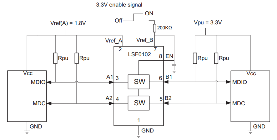
The solution is to put a series resistor on the TX line from the NTB0102 output to the FTDI RX input. I tried 4.7K resistor because that was sitting in front of me on the desk. Other values will work but I believe that a better answer is to use a bidirectional level translator for open-drain applications like the LSF0102.
The pull-up resistors cost some more board area and BOM cost but the results were perfect and the UART comes up in a known state as the system powers up. Not to mention the LSF0102 has a 3-State output enable as well. Tested both options at 38.4KBaud and both worked great.
Below is an example with pullup resistors and the LSD0102
The subtlety here is that you need to be careful of the auto direction sense circuitry. Works fine but there can be some gotchas.
PS: tried tying the TX high through a pullup but that did not work.
PPS: If there is a signal integrity concern which is generally not the case for UARTs, series ~32 Ohm resistors on TX output pins can help. For the exact resistor value you need to look at the V/I curve of the transmitter and pick the resistor value that matches the driver to the 50 Ohm Transmission line. Layout for 50Ohm T-Lines and cables. This will also cut down the risk of the EMI/EMC issues since any residual ringing is cutdown by IR drop in the terminator.
Also helps protect the output driver, although most level shifters have ESD protection of about 2.5kV (Human body model).


 RSS Feed

